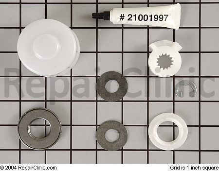
One of the indications that the brake may need adjustment is if the brake squeals during last few seconds of spin just before the tub stops. The Brake is adjustable by using the thick or thin shim washer found in the thrust bearing kit.
Before we get into checking and adjusting the Brake, it would enhance your troubleshooting arsenal to know some basic katas of how this contraption works…
Transmission Operation
When the Drive Pulley rotates CLOCKWISE, the upper and lower cams are designed to nest together which allows the Drive Pulley to remain in position on the Drive Shaft. The Brake remains engaged and the Drive Pulley will turn the lower cam and drive the shaft to cause the Transmission to agitate.
When the Drive Pulley rotates COUNTERCLOCKWISE, the upper cam and pulley ride up the lower cam approximately 3/16 of an inch before the driving shoulders on the Pulley hub engage the “dogs” on the lower cam.
This causes the top of the Pulley hub to push against the spacer which compresses the Brake Spring and lifts the Brake Rotor and lining assembly off the Brake Stator. The Brake is disengaged and the Pulley will turn the lower cam and drive shaft to cause the Transmission to spin.
Determine Brake Rotor Condition
Watch the Spacer on the encapsulated Thrust Bearing. If the Spacer rotates with the Pulley, the Brake is functioning properly. If the Spacer stays stationary while rotating the Pulley to release the Brake, the Brake Rotor must be replaced.
To Check Brake Disengagement:
1. Manually rotate the Drive Pulley in a slow COUNTERCLOCKWISE direction until the Brake starts to release and the Transmission begins to turn.
2. Attempt to position the “Reference Cam Arrow” midway between the “Min Pulley Hub Reference” and the “Max Pulley Hub Reference” markers located on the Pulley.
If you can’t get the “Reference Cam Arrow” between the markers on the Pulley Hub, then you gotta adjust the Brake.
To Adjust Brake Disengagement:
1. If the position of the Cam Reference Arrow is less than the Min Pulley Hub reference mark, remove the standard (.062 thickness) Thrust Washer and replace it with a thinner (.032 thickness) Thrust Washer. Recheck disengagement 3 times to verify proper adjustment.
2. If the position of the Cam Reference Arrow is more than the Max Pulley Hub reference mark, add a (.032 thickness) Thrust Washer to the standard Thrust Washer. Recheck disengagement 3 times to verify proper adjustment.
If you need to add a thrust washer to make the brake adjust properly, it’s usually a good idea to replace the thrust bearing kit at the same time. It includes all the washers you need.
And here’s a step-by-step guide for replacing the thrust bearing, custom-made by a Samurai Chief Apprentice Appliantologist:
Maytag Atlantic Washer Thrust Bearing Replacement, An Illustrated Guide!


