Monthly Archives: November 2008

Glassware Etching and Poor Cleaning in Whirlpool (and Kenmore) or KitchenAid Dishwashers

Now, Grasshoppah, prepare for dishwasher illumination. The Samurai is gonna reveal to you what they never tell you about fixing cleaning problems in your Whirlpool-Kenmore-KitchenAid dishwasher. So, strap yourself in and get ready to download wisdom directly from my brain to yours.

wpl-voyager-dw-motor-pump-diagramthmb.jpgFor newer-model Whirlpool and KitchenAid dishwashers (also sold under the Kenmore label with model numbers beginning with 665)– the so-called “Voyager” platform models– download this scroll for some good tips on improving cleaning performance. You can tell if you have the Voyager style by removing the front access panel (at the bottom) of the dishwasher and looking at the motor and pump layout (click the thumbnail image for a larger view).

For older model Whirlpool or KitchenAid dishwashers with the big honkin’ center-mounted motor without a separate pump, here are some tips to improve cleaning performance. Many of the tips below also apply to any dishwasher, with the obvious exception of the suggested replacement parts.

First, try these two things:

1. Use normal amounts of detergent and keep the rinse agent dispenser
supplied with rinse agent.

2. Use Hi-Temp Wash Cycle and Energy Saver Dry to allow for
proper wash action, and slower dry to allow water to sheet off the dishes.

If no joy, then we gradumutate to the more advanced stuff:

Water Hardness: Check the water with a hardness test strip. A hardness of ten grains or more may cause filming. Run a cleaning solution, such as white vinegar, through the system (refer to the “Use and Care Manual”). Other recommended cleansers for hard water situations are Glisten, or Glass Magic.

Water Temperature: Water temperature at the sink closest to the dishwasher should be between 120°F and 160°F.

Water Level: After a complete Fill cycle, check the water level in the dishwasher. The water should cover the fine mesh pump screen and part of the edge of the pump top. Check for the proper drain hose height (20 “) and verify that the dishwasher is not siphoning.

Spray Arms: Make sure that the upper and lower arms are turning freely. Check each arm for blockage and splits.

Drain: Check the dishwasher to make sure that it is draining completely. The water level in the tank after a proper drain cycle should be below the coarse strainer of the pump.

Rinse Agent Dispenser: Make sure that there is rinse agent in the dispenser, and verify that it is actually dispensing. The recommended setting is Level 2.

Detergent Lid Gasket: Check the detergent lid gasket. If the gasket is not present, install a gasket.

Check Valve: Check the pump check valve for proper operation. Listen for “gurgling” at the drain line while the dishwasher is in the Wash mode. It will indicate that the check valve flapper is leaking, allowing drained water to reenter the dishwasher. Try cleaning the gookus out of the check valve. If you still get the gurgling noise, then replace the check valve.

Pump Motor: On units built prior to code date FF47, the pump drain cover plate was the original “2-ball” design. The drain cover was replaced with a single check ball design after code date FF47. If the pump motor has not been replaced, and the unit was built prior to FF47, install the updated the pump motor assembly.

If all things listed above check okay, then replace the electronic control.

To learn more about your dishwasher, or to order parts, click here.

GE Recalls Wall Ovens Due to Fire and Burn Hazards

GE strikes again! This time, they’re recalling a quarter of a million wall ovens sold under the GE, GE Profile, Monogram and Kenmore labels.

The problem is caused by the extreme heat used in the self-clean cycle escaping if the wall oven door is removed and incorrectly re-attached by the installer or the consumer. This can pose a fire and burn hazard to the hapless folks who bought GE-built appliances.

So far, 28 incidents of minor property damage have been reported in which adjacent kitchen cabinets have been damaged. No injuries have been reported.

The wall ovens were sold in white, black, bisque and stainless steel. The following model and serial numbers can be found inside the oven on the left interior wall. For microwave combination ovens, the serial number can be found on the left interior wall of the microwave.

GE Profile

Model Numbers: JCT915, JT912, JT915, JT952, JT955, JT965, JT980*, JTP20, JTP25, JTP28, JTP48, JTP50, JTP86

Serial Numbers Begin With: TD, VD, ZD, AF, DF, FF, GF, HF, LF, MF, RF, SF, TF, VF, ZF

Monogram

Model Numbers: ZET3058, ZET938, ZET958

Serial Numbers Begin With: TD, VD, ZD, AF, DF, FF, GF, HF, LF, MF, RF, SF, TF, VF, ZF

Kenmore (All model numbers start with 911)

Model Numbers: 4771, 4775, 4781, 4904, 4905, 4923*

Serial Numbers Begin With: 2T, 2V, 2Z, 3A, 3D, 3F, 3G, 3H, 3L, 3M, 3R, 3S, 3T, 3V, 3Z

If you’re a victim of one of these appliances, you should immediately inspect the oven to make sure you don’t have an incorrectly re-attached wall oven door, which will not open into the flat position. If the wall oven door is incorrectly re-attached, consumers should not use the self-clean cycle and call GE for a free repair. You can continue to use normal baking or broiling function in the oven until the oven is repaired.

For additional information, contact GE toll-free at (888) 569-1588 between 8 a.m. and 8 p.m. Monday through Friday, and between 9 a.m. and 3 p.m. Saturday ET.

Since this problem pertains to the self-clean function, this is a good time to review the use of the self cleaning feature in an oven. During self clean, the oven can develop temperatures in excess of 900˚F. I don’t care what the manufacturers say, there isn’t a single oven built today that can withstand very many self clean cycles at these extreme temperatures. In addition to posing a potential fire hazard, using the self clean cycle will eventually cause expensive repairs in your oven such as damaged control boards and burned out temperature sensors.

So, let’s review the two rules for using the self clean feature in an oven:

Rule 1: Never, ever, ever use self clean.

Rule 2: If, in a weak moment, you find yourself thinking about using self clean, refer to Rule 1.

To learn more about your range/stove/oven, or to order parts, click here.

Older Whirlpool / Kenmore Dishwasher Won’t Drain

These were good dishwashers made back in the day when they used big ol’ honkin’ motors that jacked up the pressure on the water and blasted your dishes clean. An example model number of this vintage is DP940PWPQ2 (these dishwashers were also sold under the Kenwhore label). Alas, they just don’t make ’em like that any more. All the manufacturers have gone to these weenie designs that use a wimpy little wash motor and separate pump.

But, like all machines, these, too, had their quirks and common repairs. The difference, though, between these older Whirlpool dishwashers and the weenie ones made today is that the repairs on these older ones were usually simple and low cost, like the one I’m about to explain to you.

One common problem with these old war horses was that it wouldn’t pump the dirty water out of the basin. Typical symptoms of this problem include:

  • Crud left on dishes at the end of the wash cycle
  • Dirty water in the basin at the end of the wash cycle
  • Washer basin will not pump out

Like I said, this is usually a really easy problem to fix and, if you do it right, it usually doesn’t even require any parts. So, grab ‘hold of those lower cheeks and let’s get ready to r-r-r-umbl-l-l-l-l-l-e!

The older Whirlpool-built dishwashers used a check valve at the drain hose port in the pump housing to prevent gooky water from backing up into the basin. This check valve is prone to getting plugged up by what we professional appliantologists call, “gookus.” (This is a technical term reserved for use by professional appliantologists so please don’t use it unless you are one as I cannot be responsible for your safety.)

These check valves are prone to getting plugged up by all kinds of gookus. I’ve cleared some weird stuff out of these check valves such as:

With stuff like this running through the dishwasher, you can see that, most of the time, this problem is self-inflicted. In the immortal and wise words of my good friend from the Samurai Appliance Repair Forums, Sublime Master of Appliantology Reg, “It’s a dishwasher, not a disposal.”

whirlpool dishwasher check valve locationTo inspect the check valve for a blockage, you’ll need to remove the access panel from the dishwasher and then remove the drain hose from the check valve. This picture shows you where it be, click it for a larger view.

If the dishwasher basin is full of water and the check valve is, in fact, plugged up, then you probably won’t have to worry about water gushing out… but have a pan ready just in case. OTOH, if’n the check valve ain’t the problem and you have a basin full of gooky water, well, things could get a little messy. The Boy Scout motto applies: Be Prepared!

Usually, the plug is readily apparent as soon as you remove the drain hose from the check valve. Sometimes the cause for the plug is not immediately apparent. If you remove the drain hose from the check valve and you don’t see any gookus fall out, this just means that the blockage is further back in the check valve. In this case, you’ll need to unscrew the check valve from the pump housing to get to it.

broken check valve in an older whirlpool dishwasherThese check valves can be ornery to unscrew but persevere and ye shall overcome. Just be careful you don’t pull to the side or you might snap off the check valve, leaving part of it inside the pump housing, as shown here.

OK, that’s all there is to this bit of rocket science. Now, as our Lord Fixus done told us, “Go ye forth, therefore, and make Apprentices of all nations.”


To learn more about your dishwasher, or to order parts, click here.

Appliance Repair Tool of the Day: VersaPak Cordless Screwdriver

When you’ve turned as many screws as ol’ Samurai, you get pretty excited about cordless screwdrivers. A good cordless screwdriver can really speed up the job, eliminating some of the drudgery and saving you real time so you can go back to doing important things, like drinking beer.

What distinguishes a “good” cordless driver from a mediocre or sucky one? Some key qualifications include:

  • low cost
  • light weight
  • batteries recharge quickly
  • enough torque to get the job done
  • adjustable torque

Oh, sure, you could buy one o’ them fancy, high-dollah DEwalt drivers. But why spend all the money for a tool that you’ll probably only use once in a while when this one will do the job just as well for a fifth of the cost?

I’ve used a variation of this Black and Decker cordless driver for almost ten years now. They don’t even make the one I use anymore, guess they replaced it with this new fancy-schmancy one that you can fold into a driver gun.

The adjustable torque is an essential feature to have when working with metal screws in cheap plastic parts, which describes most appliance assemblies out there. And the adjustable torque means you’ll never again be accused of having a screw loose.

Here’s the battery you’ll need for this driver. Don’t bother with the VersaPak silver batteries. Yeah, they’re less expensive but you don’t even get what you pay for because they don’t last nearly as long as the gold batteries. Learned that the hard way. In rehab.

I’ve recycled lots of the silver VersaPak batteries because they’d no longer hold a charge. OTOH, I’ve been using the gold VersaPak batteries exclusively for over five years now and have yet to recycle a single one.


Whirlpool / KitchenAid Microwave Combination Built-In Ovens with Error Code “door”

More trouble with cheesy electronics in appliances. This time, it’s the Whirlpool-built (includes KitchenAid) built-in combination microwave ovens.

In this particular inconvenience, error code “door” appears in the display and the microwave oven shuts down in mid-cycle. When restarted, the microwave will shut down immediately again and show the “door” error code.

The microcomputer control board (more on that in a minute) will throw this error code whenever it detects an open circuit in the door interlock switch circuit (such as when the door is actually open– go figure!). Hooold on there, Bubbalouie! Uncross them eyeballs and lemme ‘splain what that means.

The door interlock switches are the little switches inside the cabinet where the door catches go in and hook when you close the door. They call ’em microswitches in the trade (I suppose to distinguish them from macroswitches).

wiring diagram or a whirlpool microwave
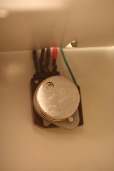
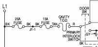
In this case, as seen in this wiring diagram, one of the components at play here is the primary interlock microswitch, usually referred to simply as a switch. To save finger strokes, we’ll refer to the primary interlock switch as the PIS, as in, “that little PISser.”

You can tell the PIS from the secondary interlock switch (the SIS- not shown here) because it’s the one with a red and black wire attached to it. How’d I know that? It’s printed right on the wiring diagram.

You see, Grasshoppah, a wiring diagram is nothing more that a road map for wires (and, more interestingly, electrons). Generally, if you can read a road map and fog a mirror, you can read a wiring diagram well enough for most DIY appliance repairs.

Anyway, you’ll need to get to the PIS (some disassembly required; unplug the microwave first and watch out for the high voltage capacitor— it holds a 2,000 volt charge… even when unplugged!). And then check the continuity of the switch while actuating it (pressing the little tab in and releasing it).

Referring again to the wiring diagram, the PIS is just one of the three components that, if open (or bad) will cause the microcomputer to throw a “door” error in the display. You’ll also notice that there are two fuses in that circuit: a 20amp and 15 amp fuse in series with each other (that means they’re on the same line). If either one of those fuses are open, you’ll get the same error in the display. So, you need to do a continuity check on both those fuses with your multimeter.

If any three of these things are open– the PIS or either of the two fuses– you’ll get “door” on the display.

microcomputer for a whirlpool or kitchenaid microwave combination ovenIf you check all those and they’re good, then you’re probably looking at a bad microcomputer control board. This microcomputer controls the operation of the microwave and monitors the position of the oven door. As you might expect, this is not something that can be adjusted or corrected by replacing the out-of-spec component on the board. No, the entire microcomputer must be replaced.

To learn more about your microwave oven, or to order parts, click here.

Microwave Oven Troubleshooting and Diagnostic Flow Chart

microwave oven troubleshooting and diagnostic flowchart

The best-kept secrets in microwave oven troubleshooting revealed! Now, for the first time ever on the internet, Samurai Appliance Repair Man, your partner in appliance repair, reveals what they don’t want you know about diagnosing and repairing your dysfunctional microwave. It’s all ratcheer in this user-friendly, quick and easy microwave oven troubleshooting flowchart. And it’s yours FREE! Download it today and share it with all your friends.


Fixitnow.com Samurai Appliance Repair Man: The planet’s #1 do-it-yourself appliance repair resource.

More microwave oven repair help:

To learn more about your microwave oven, or to order parts, click here.

The Ten Commandments for Working With Household Power

electrocuted-150x162.gif
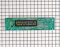
If you’re gonna work on your own appliances, you need to know something about electricity. You at least need to know what you don’t know because lots of folks think they know, but they really don’t and they end up popping a circuit breaker, getting shocked, or smoking a control board. Why? ‘Cuz they don’t know what they don’t know. Ya know?
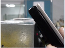
Sublime Master of Appliantology Keinokuorma, from the Samurai Appliance Repair Forums, has been to the mountain top and he has returned with the Ten Commandments for working with household electricity. Hear therefore, O Grasshoppahs, and observe to do it; that it may be well with thee, and that ye may increase mightily, as the Samurai hath promised thee, in the land that floweth with Appliantology.

The Ten Commandments of Working With Householde Power
by Sublime Master of Appliantology Keinokuorma

1. Thou shalt not worke with thy house wyres unless thou knoweth what thou art to do.

2. Thou shalt understande, that unless thou art a trained and licensed professionall elecktrician, thy work with the wyres can void thy fyre insurance.

3. Shalt thou not be sure what thou art to do, or, shalt thou at a pointe feel that thou knoweth not how to proceede, thou shalt call for the helpe of a professionall elecktrician.

4. Thou shalt turne off the breaker or remove the fuse before thou worketh on the wyres. Shalt thou not be sure which breaker or fuse affects said wyres, thou shalt turne off the main switche, and worke with a flash-lighte or candell, if no other lighte is availabel. Thou shalt checke and double checke that there is no power to the wyres thou art to worke with.

5. Unless thou knoweth for sure what thou art to do, thou shalt not tamper with the power meter or the contents of the fuse/breaker boxe. In moste installations, the meter hath Lethall Power even if thou turneth the main switche off.

6. Thou shalt not cutte the insulators when thou strippeth the outer jackett of a cabell, and thou shalt not cutte the inner wyre when thou strippeth the insulator. Thou shalt avoide using wyre nutts on stranded wyre, for that will surely cutte some strands.

7. Thou shalt not rely on elecktricall tape as finall and permanent insulation, for it could shifte and leave the bare wyre exposed. Thou shalt not truste said tape to insulate thy Screw-Driver or other metallic toole safely.

8. Thou shalt not confuse Grounde and Neutrall wyres. If thou only hath a Neutrall wyre, thou may use that for Grounde, but not the other way.

9. Thou shalt take extreme care if thou needeth to joine olde and newe wyre colors. A smallest mis-matche could leade to severe trouble.

10. Thou shalt checke and double checke thy work before thou re-seateth the fuse or turneth the main switche or breaker on.

If thou faileth to heede these warnings, thou standeth the great riske of feeling the Wrathe of The Power in its full effect with the moste un-desirabell resulte.

———————

Additionall Notes to Severall Commandments

4: Thou may make an exception if thou needeth to verify the funcktionality of the circuite, or verify which fuse or breaker affecteth it. Taking great care, and with suitabell and reliabell measuring devices, thou may verify if the circuite is powered or not. Thou shalt not rely upon the Glow-Sticke or Contackt Voltage Indicator but for reference only. Thou shalt acquire a Digitall or Analogue Multi-Meter which giveth thou true readings, and thou shalt learne to operate thy Multi-Meter before thou worketh on thy house wyres. Any shoppe with good stocke of elecktricall stuffe will be happy to sell one.
Basick Measurements Guide.

5: In moste cases, thou shalt leave any alterations to the breaker boxe to the professionall elecktrician.

Overall: Thou shalt leave any extensive alterations to any circuite to a professionall elecktrician. In any case, thou shalt make a neate, comprehendibel jobbe that shalt not confuse those who worke on it at later tymes.

Can I hear an “Amen?”

How to Remove the Control Panel on a Frigidaire Wall Oven

frigidaire-walloven-control-panel.jpgRemoving the control panel on a wall oven can be tricky. On some brands, such as the Frigidaire, you need to actually remove the walloven from the cabinet just to remove the control panel. Why they design it like this, I’ll never understand. Nevertheless, this is but one of a plethora of joys we encounter in the field running service calls. This scroll from the Appliantology scriptures will show you how to remove the control panel without breaking anything… too much.

To learn more about your range/stove/oven, or to order parts, click here.

The Permanent Cure for Repeated Frost-Up Problems in a Maytag Side-By-Side Refrigerator

Defrost system failures are a common problem in the Maytag (and Jenn-Air) refrigerators with the Automatic Defrost Control (ADC) boards. Most of the time, the cause of the problem is that the ADC board has failed. Master Appliantologist AZBen has developed and field-tested an ingenious field modification that vastly improves the reliability of the defrost system by replacing the ADC board with the good ol’ mechanical defrost timer. Simple, rugged, and much less expensive than a replacement ADC board. Here’s how he did it:

I’ve been fighting this failed defrost for several months. Fortunately in AZ we don’t get enough humidity for it to frost up very fast… over 3 months between incidents. So being somewhat like the old adage “the cobbler’s children have no shoes”, I did not rush to figure this out, just defrost and go… until I got really aggravated about it.

Then I read all the forums I could about the MSD2756DEW and how it is prone to frosting problems. I saw that the adaptive defrost control circuit board was anywhere from 40 to 55 dollars, and difficult to test, so I had a discussion with the counter help at Johnstone Supply where I buy AC parts. With the wiring diagram, found beside the defrost control board, I was able to match up the B10-988 mechanical timer and 4 of the 5 wires on the original circuit board. The white with black stripe wire is not needed because it is the sensor wire. Using the mechanical timer we will rely on the sensor to open the defrost circuit, but we do not need that information back at the new fixed interval (non-adaptive) timer.

The wires used are Orange (compressor), Yellow (defrost), White (common or neutral), and Red (L1 or hot). At the defrost control the red wire is used only to power the board or the timer motor… power is already applied to the orange and yellow wires and is to be directed through the timer or circuit board back to the white (neutral). So think in terms of grounding the circuit you want to complete. The B10-988 timer has a color code which you can translate as follows: Terminal 1 labeled R is connected to Maytag red wire, Terminal 2 labeled BL is connected to Maytag yellow wire, Terminal 3 labeled OR is connected to Maytag white wire, and Terminal 4 labeled BK is connected to Maytag orange wire.

Once I had the new timer working, I could hear the defrost cycle start with a click and the cabinet lights dimmed, but just for a few seconds. You can make the defrost cycle start by turning the small plastic wheel protruding through the timer back, but you need to do this with a meter attached to see when the contacts close between 2 and 3 (yellow to white wire). A quick check with my fingers and I found that the defrost heating element was still cold. Do this cautiously because when it works it will be red scorching hot and will not be something you want to touch. I moved very slowly toward it to see if the element was hot at the lowest point in the loop.

So I had a second problem, or I have a spare circuit board. Either way, I’m tired of guessing when the defrost cycle is working, so the spinning of the timer flywheel — visible through the clear window — is reassuring and I have mounted it so I can see it without removing the plastic cover in the top of the refrigerator. Now I attempted to slip the pins out of the defrost coil plug, but I did not have the right size tube to hit the release. This would have allowed me to redirect the blue power lead directly to the heating element on the white with black stripe wire, without going through the thermocouple switch. So with the plug pulled, I cut out the thermocouple switch then soldered and shrink tubed the solid white wires together. After plugging back into the 3-pin connector, then forcing the timer to switch back to defrost (the 25 minute cycle ended well before I finished the splice), I immediately got dimmed cabinet lights and a glowing defrost element.

I tested the thermocouple switch that I removed, by putting it into a deep freeze at 0F. It had high resistance, above 100 ohms, too high to power up a heating element that shows only about 20 ohms cold.

Now I have a situation where the defrost cycle will stay on for a full 25 minutes each 6 hours, not the way I want to run. However, observation of the next 18 hours and 3 defrost cycles shows that the element is not overheating the cabinet or scorching the paint on the front cover. This gives me time to locate the replacement switch and re-install it without having to buy the full Maytag assembly… or the PartSelect PS890605 (38.08 with shipping), the only way it is sold is with the heating element and 3-pin plug. The thermocouple switch is marked with a small symbol and CT-7SB 43F 77159-16 3270. I believe 43F or above is the temperature to open the contacts inside.

BTW, don’t be surprised if you have problems with the little tabs breaking off when you slide the top cover out of the refrigerator to access the adaptive defrost control circuit board. Both tabs broke off even though I was very careful. I believe they had sort of fused into the similar plastic of the cover. When I replaced the cover I pushed it up over the remaining part, so that the slot was filled, then ran a screw into each side in the crack. This pulled the cover up snug and keeps it from sliding forward where it could drop off of the front support tabs. The photo shows my defrost timer and the screw to hold the cover where the tab broke off.

Finally I took my owners manual, wiring diagram (from near the adaptive defrost control), receipt for new timer, and wiring modification notes — and placed all these into a large zip lock bag which sits below the bottom drawer in the refrigerator side. A small piece of blue painters tape keeps it from slipping around and no one notices it since it barely protrudes from under the drawer.

AZBen

Update about the photo… the green ground wire is spliced into a green ground wire in the wiring harness above. There was not a ground wire going to the original defrost control board.

field modification of the defrost timer in a Maytag-built refrigerator with ADC

To learn more about your refrigerator, or to order parts, click here.